Professional China PCB Assembly Online Services
Prototyping boards, also known as breadboards, are essential tools for electronics enthusiasts and professionals who want to test and debug their circuits before making a permanent PCB. Prototyping boards allow you to easily insert and remove components, wires and jumper cables without soldering, making them ideal for experimenting with different designs and configurations. In this article, we will cover some of the basics of prototyping boards, such as soldering techniques, solder bridging methods, wiring tips, and how to use them effectively. We will also discuss the relationship between prototyping boards and PCBs, and how you can design and fabricate your own prototyping circuit boards. Finally, we will explore some of the applications of prototype expansion boards, which are special boards that extend the functionality of your prototyping board with additional features and modules.
Although prototyping boards are designed to be used without soldering, there are some cases where you may want to solder some components or wires to your board for a more secure and reliable connection. For example, you may want to solder a power supply connector, a switch, a potentiometer, or a header pin to your board. Soldering on a prototyping board is similar to soldering on a PCB, but there are some differences and challenges that you need to be aware of.
One of the main challenges is that prototyping boards have many holes that are connected by metal strips underneath. This means that when you apply heat to one hole, you may unintentionally heat up other holes and components nearby, causing them to melt or damage. To avoid this, you need to use a low-wattage soldering iron with a fine tip, and apply heat only for a short time. You also need to be careful not to touch the metal strips with your soldering iron, as this may create unwanted connections or shorts.
Another challenge is that prototyping boards have plastic bases that can melt or deform when exposed to high temperatures. To prevent this, you need to use a heat-resistant mat or pad under your board, and avoid placing your soldering iron directly on the board. You also need to use a low-temperature solder with a low melting point, such as 60/40 tin-lead alloy.
To solder a component or wire to your prototyping board, follow these steps:
1. Insert the component or wire into the desired hole on the board.
2. Bend the leads or wires slightly to hold them in place.
3. Heat up your soldering iron and tin the tip with some solder.
4. Apply some flux to the joint area to improve the flow of solder.
5. Touch the tip of your soldering iron to the joint area and wait for a few seconds until it heats up.
6. Feed some solder to the joint area until it forms a smooth and shiny cone around the lead or wire.
7. Remove the soldering iron and let the joint cool down.
8. Cut off any excess leads or wires with wire cutters.
9. Check the joint for any cold solder joints, bridges, or shorts, and fix them if necessary.
Prototyping boards and PCBs are both types of circuit boards that allow you to connect electronic components and create circuits. However, they have different purposes and advantages.
Prototyping boards are mainly used for testing and debugging purposes, as they allow you to easily change and modify your circuit without permanent consequences. They are also cheaper and faster than PCBs, as they do not require any special equipment or materials. However, prototyping boards have some limitations and drawbacks as well. They are not suitable for complex or high-frequency circuits, as they have high resistance, capacitance, and inductance that can affect the performance of your circuit. They are also not very durable or reliable, as they can suffer from loose connections, corrosion, or damage over time.
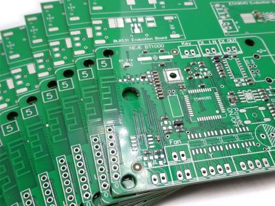
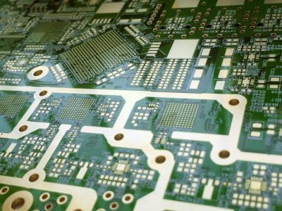
PCBs are mainly used for final products or applications that require high quality and reliability. They are designed and fabricated using specialized software and machines that create precise and accurate traces and pads on a copper-clad board. They can handle complex and high-frequency circuits with minimal interference or noise. They are also more durable and reliable than prototyping boards, as they have stronger and more stable connections that can withstand harsh environments and conditions.
The relationship between prototyping boards and PCBs is not mutually exclusive. In fact, they are often used together in different stages of the development process. For example, you may use a prototyping board to test your circuit idea and make sure it works as expected. Then, you may use a PCB design software to create a schematic diagram and layout of your circuit on a virtual board. Next, you may use a PCB fabrication service or machine to produce your physical PCB based on your design file. Finally, you may use a prototyping board again to test your PCB before mounting it on your final product or application.
Solder bridging is a technique that allows you to create connections between different holes or rows on your prototyping board using solder. This can be useful when you need to connect components or wires that are not adjacent or aligned on your board, or when you run out of jumper cables or wires. Solder bridging can also create more compact and neat circuits, as it reduces the amount of wires and cables on your board.
There are different methods of solder bridging, depending on the type and shape of the connection you want to make. Here are some of the most common methods:
- Wire bridging: This method involves using a thin and flexible wire, such as a resistor lead or a jumper wire, to connect two holes or rows on your board. You simply insert the wire into the holes or rows, bend it to the desired shape, and solder it in place. This method is easy and versatile, as you can create any shape or angle of connection with the wire. However, this method can also create messy and cluttered circuits, as the wire can take up a lot of space and interfere with other components or wires on your board.
- Solder blob bridging: This method involves using a large amount of solder to create a blob that connects two holes or rows on your board. You simply apply heat and solder to one hole or row, and then drag the soldering iron to the other hole or row, creating a blob of solder that spans across them. This method is quick and simple, as you do not need any additional materials or tools. However, this method can also create unreliable and unsafe circuits, as the blob of solder can easily melt or break, causing shorts or open circuits. Moreover, this method can also damage your board or components, as the blob of solder can touch the metal strips or plastic base of your board, creating unwanted connections or melting the plastic.
- Solder wick bridging: This method involves using a braided copper wire, also known as solder wick or desoldering braid, to connect two holes or rows on your board. You simply cut a piece of solder wick that is slightly longer than the distance between the holes or rows, insert it into the holes or rows, and solder it in place. This method is neat and reliable, as the solder wick creates a thin and flat connection that does not take up much space or interfere with other components or wires on your board. Moreover, this method can also remove excess solder from your board, as the solder wick absorbs the solder when heated. However, this method can also be tricky and expensive, as you need to use a good quality solder wick that does not fray or burn easily, and you need to use more solder than usual to fill up the gaps in the solder wick.
Prototyping boards are easy to use once you understand how they work and how to connect components and wires on them. Here are some general instructions on how to use prototyping boards:
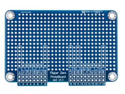
1. Choose a suitable prototyping board for your project. There are different types and sizes of prototyping boards available in the market, such as full-size, half-size, mini-size, etc. You should choose a prototyping board that has enough holes and rows for your circuit components and wires. You should also consider the type of power supply you will use for your circuit, as some prototyping boards have built-in power rails that can provide 5V or 3.3V power from a battery or an adapter.
2. Plan your circuit layout on your prototyping board. Before inserting any components or wires on your board, you should have a clear idea of how you want to arrange them on your board. You can use a pencil and paper to sketch out your circuit diagram and layout, or use a software tool such as Fritzing to create a virtual representation of your circuit on a prototyping board. You should try to make your circuit layout as simple and compact as possible, avoiding crossing wires or components that may cause shorts or interference.
3. Insert your components into the holes on your prototyping board. You should start with the main components of your circuit, such as microcontrollers, sensors, LEDs, etc., and then add the supporting components such as resistors, capacitors, etc. You should insert the components according to their polarity (if applicable), making sure that their positive and negative leads are connected to the correct holes or rows on your board. You should also bend the leads slightly after inserting them to hold them in place.
4. Connect your components with wires or jumper cables. You should use wires or jumper cables of different colors to connect different parts of your circuit, such as power supply, ground, input/output signals, etc. You should insert the wires or jumper cables into the holes that are connected to the leads of your components by metal strips underneath your board. You should also try to make your connections as short and straight as possible.
If you are interested in electronics, you may have come across the terms breadboard and prototyping board. But what are they and how are they different? In this article, we will explain the main features and functions of these two types of boards, and how to choose the best one for your project.
Breadboards are boards that allow you to quickly and easily connect electronic components without soldering. They have rows of holes that are connected internally by metal strips, forming a grid of electrical connections. You can insert wires, resistors, LEDs, capacitors, transistors, and other components into the holes, and create circuits by connecting them to a power source and a ground.
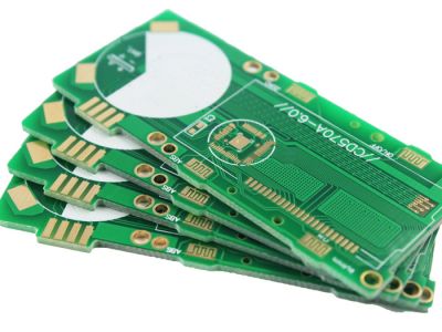
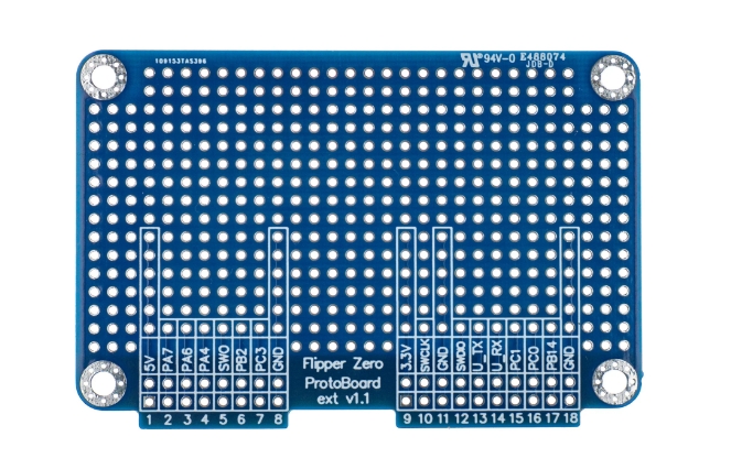
Prototyping boards, also known as perfboards or stripboards, are boards that have holes drilled in a regular pattern, but without any internal connections. They are usually made of fiberglass or plastic, with a thin layer of copper on one or both sides. To create circuits on prototyping boards, you need to solder the components and wires to the copper pads or strips, forming permanent connections.
The main difference between breadboards and prototyping boards is that breadboards are temporary and reusable, while prototyping boards are permanent and non-reusable. Breadboards are ideal for testing and experimenting with different circuit designs, as you can easily change or remove components without damaging them. Prototyping boards are suitable for making final or more durable versions of your circuits, as they provide more stability and reliability.
Another difference is that breadboards have a standard layout and size, while prototyping boards come in various shapes and dimensions. Breadboards usually have two power rails on each side, where you can connect the positive and negative terminals of your power source. They also have a central gap that separates the rows of holes into two sections, each with five columns. Prototyping boards can have different numbers and arrangements of holes, pads, and strips, depending on the manufacturer and model.
A third difference is that breadboards are easier and faster to use than prototyping boards, but also more limited and expensive. Breadboards do not require any soldering skills or tools, and you can quickly assemble and disassemble your circuits by plugging in or pulling out the components. However, breadboards have some drawbacks, such as:
- They can be bulky and unstable, especially for large or complex circuits.
- They can have poor electrical contacts or loose connections, leading to noise or errors in your circuit.
- They can have limited current capacity or voltage range, which may damage your components or board.
- They can be more expensive than prototyping boards in the long run, as you may need to buy multiple breadboards or accessories to accommodate your circuit needs.
Prototyping boards require more time and effort to use than breadboards, as you need to solder the components and wires carefully and neatly. However, prototyping boards have some advantages, such as:
- They can be more compact and sturdy, especially for small or simple circuits.
- They can have better electrical contacts or connections, resulting in less noise or errors in your circuit.
- They can have higher current capacity or voltage range, which may protect your components or board from damage.
- They can be more cost-effective than breadboards in the long run, as you only need to buy one board for each circuit.
To summarize, breadboards and prototyping boards are two types of boards that allow you to create electronic circuits. Breadboards are temporary and reusable boards that let you connect components without soldering. Prototyping boards are permanent and non-reusable boards that require you to solder components to copper pads or strips. The choice between breadboards and prototyping boards depends on your project goals, preferences, skills, budget, and availability.