Table of Contents:
1.Introduction
The Evolution of Circuit Card Assembly (CCA)
What is a Circuit Card Assembly?
2.Understanding Circuit Card Assembly (CCA)
Defining CCA and Its Significance
The Distinction Between CCA and PCB (Printed Circuit Board)
3.Methods of Circuit Card Assembly
Manual Method
Semi-Automated Method
Automated Method
4.Steps in Circuit Card Assembly+
Mold Design and Production
Design Phase
Creation Phase
Packaging
PCB Manufacturing
CAD System
Circuit Design
Gerber Generation
Sub-Assembly
Forming
Testing
5.Best Mounting Techniques for CCA
Surface Mount Technology (SMT)
Ball Grid Array (BGA)
Thru-Hole Technology (THT)
T and R (Test and Repair)
6.Considerations Before Choosing a CCA Service Provider
Quality Standards
Technical Expertise
Industry Reputation
Cost Considerations
7.Applications of CCA
Electronics Industry
Aerospace and Defense
Medical Devices
Automotive Sector
8.Advantages of Circuit Card Assembly
Increased Reliability
Space Efficiency
Enhanced Performance
9.Disadvantages of Circuit Card Assembly
Initial Cost
Limited Repair Options
Environmental Concerns
Conclusion
Recap of Circuit Card Assembly Evolution
Future Trends in CCA
Related Posts:
Exploring the Intricacies of Mold Design in Circuit Card Assemblies
Revolutionizing Electronics: The Role of CAD Systems in CCA
SMT vs. THT: Choosing the Right Mounting Technology for Your CCA
The Impact of Circuit Card Assembly in the Automotive Industry
In the dynamic landscape of modern electronics, where innovation and precision intertwine, the evolution of Circuit Card Assembly (CCA) stands as a testament to the relentless pursuit of efficiency and performance. From its inception to its diverse applications across industries, CCA has become a cornerstone in the realm of electronic design and manufacturing.
This comprehensive guide aims to navigate the intricate journey of Circuit Card Assembly, unveiling its historical roots, defining its significance, and exploring the methods that have shaped its existence. As we delve into the manual, semi-automated, and automated techniques employed in CCA, a tapestry of meticulous steps emerges, each contributing to the seamless integration of electronic components.
Mold design, circuit creation, and packaging intricacies lay the foundation for the subsequent stages, where Printed Circuit Board (PCB) manufacturing takes center stage. From the utilization of CAD systems to circuit design, Gerber generation, sub-assembly, forming, and testing, this guide dissects each step in the assembly process.
Mounting technologies play a pivotal role in the performance of Circuit Card Assemblies, and we will explore the nuances of Surface Mount Technology (SMT), Ball Grid Array (BGA), Thru-Hole Technology (THT), and the critical T and R (Test and Repair) processes.
Yet, the journey doesn't end with the assembly itself. Choosing a CCA service provider involves a careful consideration of factors such as quality standards, technical expertise, industry reputation, and cost implications.
As we traverse the expansive landscape of CCA, we will uncover its diverse applications across the electronics, aerospace, defense, medical, and automotive sectors. Simultaneously, we will weigh the advantages of CCA, including increased reliability and space efficiency, against its inherent challenges, such as initial costs and limited repair options.
Embark on this exploration with us, as we unravel the layers of Circuit Card Assembly, providing insights into its past, present, and future, and offering a comprehensive understanding of its role in shaping the electronic landscape.
1.The Evolution of Circuit Card Assembly (CCA)
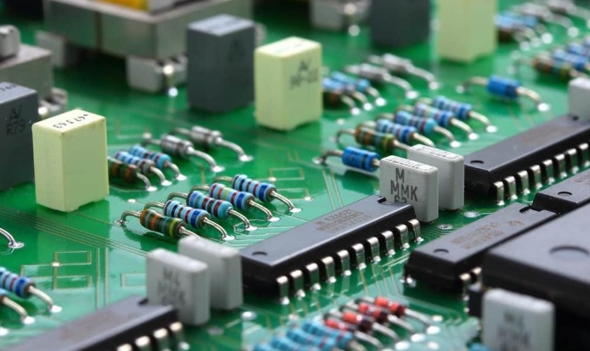
Circuit Card Assembly (CCA) has undergone a remarkable evolution since its inception, marking a transformative journey in the realm of electronic manufacturing. This evolution is not only a testament to the relentless pursuit of technological advancements but also a response to the escalating demands for compact, efficient, and high-performance electronic systems.
Early Days: The Birth of Circuit Card Assembly
The origins of Circuit Card Assembly can be traced back to the mid-20th century when the electronics industry was burgeoning with innovation. As electronic devices became more complex, the need for a standardized method of assembling components arose. The birth of Circuit Card Assembly can be seen as a solution to this challenge, streamlining the assembly process and paving the way for more sophisticated electronic systems.
Manual Assembly to Automation: The Technological Leap
In its nascent stages, Circuit Card Assembly predominantly relied on manual assembly methods. Skilled technicians meticulously soldered components onto circuit boards, a time-consuming and labor-intensive process. However, with the advent of automation and robotics in the latter half of the 20th century, the landscape of CCA underwent a profound transformation. Automated assembly lines emerged, bringing efficiency, precision, and scalability to the production of electronic devices.
Integration of CAD Systems: Precision in Design and Manufacturing
One of the pivotal moments in the evolution of CCA was the integration of Computer-Aided Design (CAD) systems. This technological leap allowed for the digital representation of circuit designs, enabling engineers to simulate and optimize layouts before physical implementation. CAD systems not only enhanced the accuracy of designs but also facilitated seamless communication between design and manufacturing processes, reducing errors and improving overall efficiency.
Surface Mount Technology (SMT) Revolution: Compact and High-Performance Assemblies
The introduction of Surface Mount Technology (SMT) marked a paradigm shift in Circuit Card Assembly. SMT replaced the traditional through-hole component mounting with components mounted directly onto the surface of the circuit board. This innovation not only reduced the size of electronic devices but also improved their performance by minimizing signal propagation delays and optimizing component placement.
Current Trends and Future Prospects
In the present era, Circuit Card Assembly continues to evolve with advancements in materials, miniaturization, and smart manufacturing. Emerging technologies such as 3D printing and the Internet of Things (IoT) are influencing the design and production of CCAs, opening new possibilities for interconnected and intelligent electronic systems.
The evolution of Circuit Card Assembly is a dynamic narrative that reflects the collaborative efforts of engineers, designers, and manufacturers striving to push the boundaries of electronic innovation. As we navigate the intricate steps and methods of CCA in this guide, it is crucial to appreciate the historical context that has shaped this indispensable component of the modern technological landscape.
2.What is a Circuit Card Assembly?
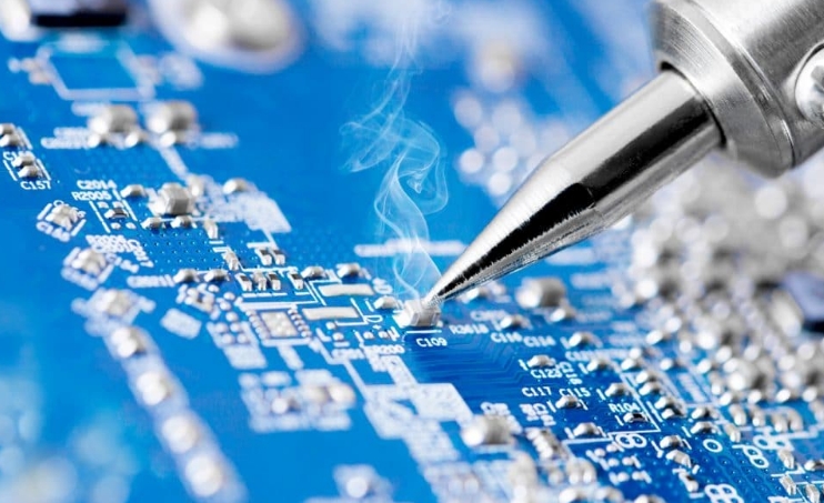
A Circuit Card Assembly (CCA) is a crucial component in the realm of electronic manufacturing, serving as the backbone for the construction of various electronic devices. Also commonly known as a circuit card or simply a circuit board, a CCA is a physical platform that provides support and interconnectivity for electronic components to form a functional electronic circuit.
Key Components of a Circuit Card Assembly:
Substrate or Base Material: The foundation of a CCA is typically a rigid or flexible substrate, commonly made of materials like fiberglass-reinforced epoxy (FR-4) for rigid boards or polyimide for flexible boards.
Conductive Traces: Copper foil is laminated onto the substrate to create conductive pathways, known as traces. These traces facilitate the flow of electrical signals between various components on the circuit.
Electronic Components: Integrated circuits (ICs), resistors, capacitors, transistors, and other electronic components are mounted on the circuit board. These components perform specific functions within the overall electronic system.
Solder Mask: A protective layer, often in the form of a solder mask, is applied over the circuit to insulate the conductive traces and prevent unintentional electrical contact.
Silkscreen: Information such as component labels, reference designators, and test points may be printed on the circuit board using a silkscreen layer.
Functions and Significance:
The primary function of a Circuit Card Assembly is to provide a platform for the integration of electronic components, facilitating the creation of complex electronic circuits. CCAs are integral to electronic devices, ranging from simple consumer electronics to highly sophisticated aerospace and medical equipment.
Advantages of Circuit Card Assemblies:
Compact Design: CCAs enable the creation of compact electronic devices by organizing and arranging components efficiently on a single board.
Ease of Manufacturing: The standardized design and manufacturing processes associated with CCAs streamline production, leading to cost-effectiveness and reproducibility.
Repair and Maintenance: In the event of a component failure, CCAs can be more easily replaced or repaired compared to individual components on a complex circuit.
Customization: CCAs allow for the creation of customized electronic circuits tailored to specific applications and requirements.
Types of Circuit Card Assemblies:
Single-Layer PCBs: Used in simpler electronic applications with fewer components.
Double-Layer PCBs: More common, with components mounted on both sides of the circuit board.
Multi-Layer PCBs: Employed in complex electronic systems, featuring multiple layers of substrate and interconnected traces.
In summary, a Circuit Card Assembly is a foundational element in electronic design and manufacturing, providing a platform for the integration and interconnection of electronic components to create functional electronic circuits.
3.Defining circuit card assembly and Its Significance
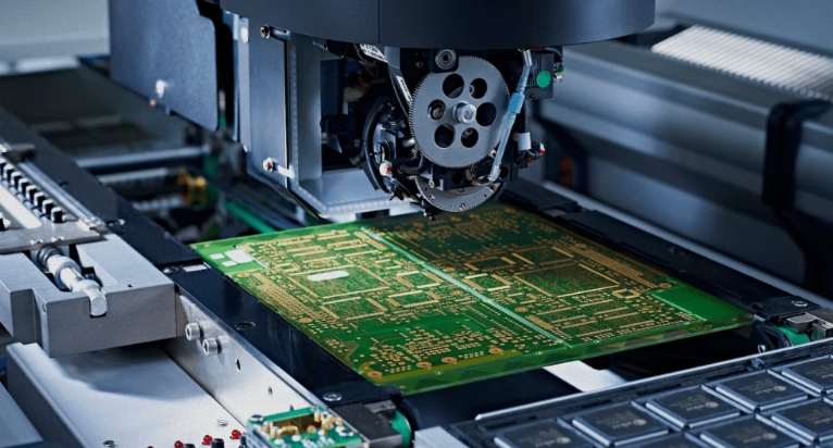
Circuit Card Assembly (CCA) refers to the process of assembling electronic circuits on a printed circuit board (PCB). It involves the integration of various electronic components, such as resistors, capacitors, integrated circuits, and other active and passive devices, onto a PCB to create a functional electronic circuit. The components are soldered onto the PCB, and the assembly may include both surface-mount and through-hole components.
Here's a breakdown of the key aspects of Circuit Card Assembly and its significance:
1.Components Integration:
Circuit Card Assembly involves the integration of electronic components onto a PCB. This includes placing and soldering components to create the desired electrical connections and pathways.
2.Printed Circuit Board (PCB):
The foundation of CCA is the PCB, which provides a platform for mounting and connecting electronic components. PCBs are designed with specific circuit layouts, traces, and layers to accommodate the electrical requirements of the circuit.
3.Soldering:
Soldering is a critical process in CCA. It involves melting solder to create electrical connections between the components and the PCB. Proper soldering ensures reliable and durable connections.
4.Surface Mount Technology (SMT) and Through-Hole Technology (THT):
CCA can involve both SMT and THT. SMT components are mounted directly onto the surface of the PCB, while THT components have leads that go through holes in the PCB and are soldered on the other side. The choice between SMT and THT depends on the design requirements and the type of components used.
5.Quality Control and Testing:
After assembly, CCAs undergo rigorous quality control and testing processes to ensure that the assembled circuits meet specified standards and operate as intended. This may include visual inspection, automated testing, and functional testing.
6.Significance:
Efficient Production: CCA is crucial in the mass production of electronic devices. By automating the assembly process, manufacturers can produce electronic circuits efficiently and cost-effectively.
Miniaturization: The ability to densely pack components onto a PCB allows for the miniaturization of electronic devices. CCAs play a vital role in the development of compact and lightweight electronic products.
Reliability: Properly assembled CCAs contribute to the reliability of electronic systems. Quality soldering and assembly processes ensure stable electrical connections, reducing the risk of malfunctions and failures.
Customization: CCAs enable the production of custom electronic circuits for specific applications. Designers can tailor the layout and components to meet the requirements of particular electronic devices.
Technology Advancements: Advances in CCA technology, including automated assembly and inspection, contribute to the continuous improvement of electronic devices, making them more sophisticated, efficient, and reliable.
In summary, Circuit Card Assembly is a fundamental process in the manufacturing of electronic circuits. Its significance lies in its role in efficient production, miniaturization, ensuring reliability, customization, and contributing to technological advancements in the electronics industry.
4.The Distinction Between CCA and PCB (Printed Circuit Board)
Circuit Card Assembly (CCA) and Printed Circuit Board (PCB) are related concepts in the field of electronics, but they refer to different aspects of the electronic manufacturing process. Here's a distinction between CCA and PCB:
Printed Circuit Board (PCB):
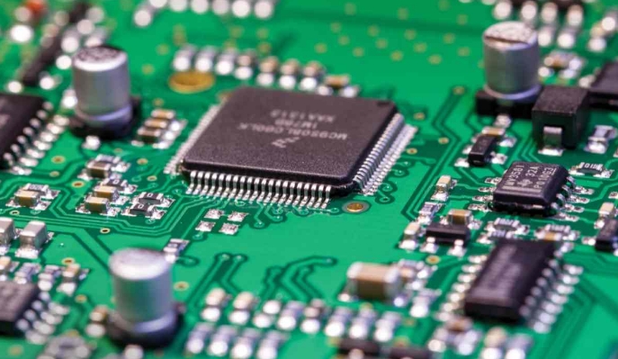
Definition: A PCB is a physical board or substrate made of insulating material, typically fiberglass-reinforced epoxy, with conductive pathways etched or printed onto its surface. These conductive pathways form the electrical connections between electronic components mounted on the board.
Function: The primary function of a PCB is to provide a platform for mounting and connecting electronic components in a structured and organized manner. It serves as the foundation for the electrical connections within an electronic circuit.
Components: A PCB includes conductive traces, pads, and sometimes planes that form the circuit's layout. It may have multiple layers to accommodate complex circuits. PCBs can be single-sided, double-sided, or multilayered, depending on the complexity of the circuit.
Circuit Card Assembly (CCA):
Definition: CCA refers to the process of assembling electronic components onto a printed circuit board (PCB) to create a functional electronic circuit. It involves the integration of various components onto the PCB, including resistors, capacitors, integrated circuits, and other active and passive devices.
Function: The main function of CCA is to bring together all the necessary electronic components onto the PCB, creating a complete and functional electronic circuit. This process includes placing, soldering, and testing the components on the board.
Production: CCA is a stage in the larger process of electronic device manufacturing. It involves the physical assembly of the components onto the PCB, transforming the bare PCB into a fully functional circuit board.
In summary:
PCB refers to the physical board with conductive pathways used for mounting and connecting electronic components.
CCA refers to the process of assembling electronic components onto a PCB to create a functional electronic circuit.
Essentially, a PCB is the static, physical foundation, while CCA is the dynamic process of populating that foundation with electronic components to make a working circuit. The distinction lies in the static vs. dynamic nature of the concepts, with the PCB being the static board and CCA being the active assembly process.
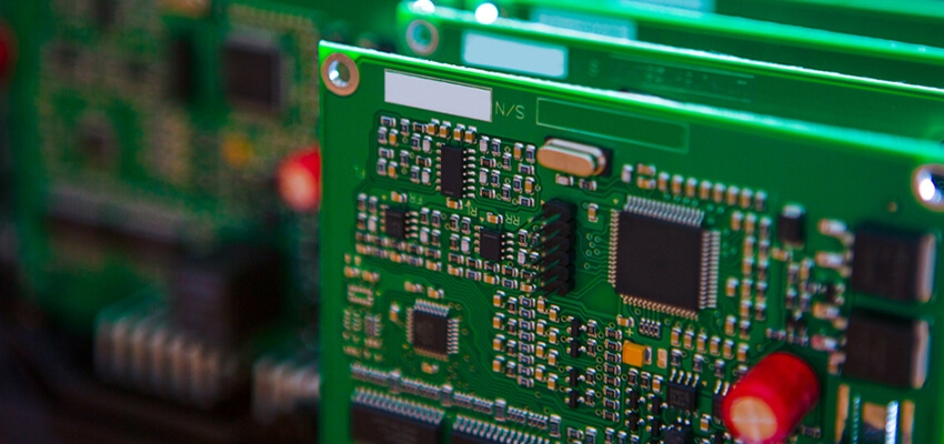
Exploring the Intricacies of Mold Design in Circuit Card Assemblies
Mold design in the context of circuit card assemblies (CCAs) is a crucial aspect of ensuring the reliability, durability, and performance of electronic devices. The primary purpose of molding in CCAs is to protect electronic components from environmental factors, mechanical stress, and potentially harmful substances. Here are some key aspects to consider when exploring the intricacies of mold design in circuit card assemblies:
1. Material Selection:
Thermal Conductivity: The material used for molding should have suitable thermal conductivity to dissipate heat generated by electronic components.
Dielectric Properties: Insulating materials are crucial to prevent electrical interference or short circuits. Materials with low dielectric constant and loss tangent are often preferred.
2. Environmental Considerations:
Temperature Resistance: The molding material should withstand the operating temperature range of the electronic components.
Chemical Resistance: Protection against exposure to chemicals, moisture, and other environmental factors is essential.
3. Mechanical Protection:
Shock and Vibration Resistance: Design the mold to absorb and dissipate mechanical shocks and vibrations to protect delicate components.
Structural Integrity: Ensure that the mold provides structural support to the components and prevents flexing or bending.
4. Customization for Components:
Component-Specific Molding: Design the mold to accommodate various types and sizes of components, ensuring a secure fit for each.
Accessibility: Consider ease of access for maintenance or replacement of components.
5. Mold Complexity:
Parting Lines and Draft Angles: Proper parting lines and draft angles facilitate easy mold release and reduce the risk of defects in the molded parts.
Cavities and Undercuts: Address any complex features or undercuts in the design to ensure a successful molding process.
6. Quality Control and Tolerance:
Tight Tolerances: Maintain tight tolerances to ensure that the molded components fit precisely within the assembly.
Quality Assurance: Implement measures to monitor and control the quality of the molded parts throughout the production process.
7. Manufacturability:
Moldability: Consider the manufacturability of the design, ensuring that it can be effectively molded without causing defects.
Injection Molding Parameters: Optimize parameters such as injection pressure, temperature, and cooling time for efficient production.
8. Compliance and Standards:
RoHS Compliance: Ensure that the molding materials comply with environmental standards such as the Restriction of Hazardous Substances (RoHS) directive.
IPC Standards: Adhere to relevant standards set by the Institute for Printed Circuits (IPC) for electronic assemblies.
9. Cost Considerations:
Material Costs: Evaluate the cost-effectiveness of the molding materials while meeting the required performance criteria.
Tooling Costs: Consider the costs associated with mold fabrication and factor them into the overall project budget.
10. Future Considerations:
Scalability: Design molds that can be easily scaled for mass production.
Adaptability: Consider potential future changes in electronic components or assembly processes that may necessitate modifications to the mold.
Effective mold design in circuit card assemblies involves a multidisciplinary approach, integrating knowledge from materials science, electronics, and manufacturing processes. Collaboration between design engineers, materials experts, and manufacturing specialists is key to developing robust and reliable mold designs for electronic components.
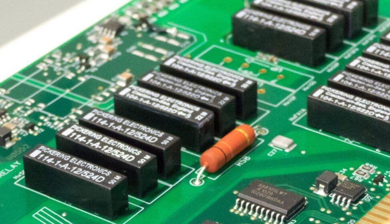
Methods of Circuit Card Assembly
There are several methods and steps involved in the circuit card assembly process. Here are some key methods:
1.Surface Mount Technology (SMT):
Placement: SMT involves placing electronic components directly onto the surface of the PCB. This is done using automated pick-and-place machines that precisely position components on the board.
Soldering: Solder paste, a mixture of solder and flux, is applied to the PCB. The components are then heated in a reflow oven, causing the solder to melt and create electrical connections.
2.Through-Hole Technology (THT):
Component Insertion: Through-hole components have leads that go through holes in the PCB. Components are manually or automatically inserted into these holes.
Wave Soldering: The PCB is passed over a wave of molten solder, which makes contact with the exposed leads on the bottom of the PCB, creating solder joints.
3.Mixed Technology Assembly:
Combination of SMT and THT: Some assemblies use a combination of SMT and THT components. SMT is often used for smaller and more densely populated components, while THT is used for larger components or those requiring additional mechanical support.
4.Automated Assembly:
Pick-and-Place Machines: These machines are used for accurate and high-speed placement of surface mount components onto the PCB.
Automated Optical Inspection (AOI): AOI systems check for defects in the assembly, ensuring correct component placement and soldering.
5.Manual Assembly:
Hand Soldering: Skilled technicians may manually solder components, especially for prototypes, low-volume production, or components that are not suitable for automated processes.
6.In-Circuit Testing (ICT):
Functional Testing: After assembly, the circuit is tested for functionality. In-circuit testing involves checking individual components and connections to ensure they meet specifications.
7.Quality Control and Inspection:
Visual Inspection: Technicians visually inspect the assembled PCBs for defects such as solder bridges, missing components, or misalignment.
X-ray Inspection: X-ray machines can be used to inspect hidden solder joints and identify defects that may not be visible to the naked eye.
8.Conformal Coating:
Protective Coating: A conformal coating may be applied to protect the PCB from environmental factors such as moisture, dust, and chemicals.
9.Rework and Repair:
Component Replacement: In case of defects or failures, rework stations may be used to replace or repair individual components.
These methods are often part of a larger quality control and assurance process to ensure that the final circuit card assembly meets the required specifications and standards. The specific methods used can vary based on factors such as the type of components, production volume, and the complexity of the circuit.