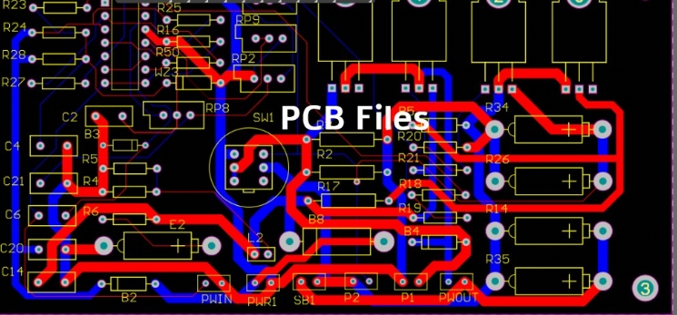
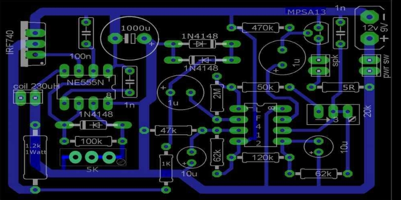
Printed Circuit Boards (PCBs) are the backbone of modern electronic devices, serving as the foundation for electrical connections and component placement. During the development and production stages, various file types are required to communicate design details with PCB manufacturers. This article explores the essential file types used in PCB design, fabrication, and assembly processes, emphasizing their roles and the information they convey.

The initial step in creating a PCB is designing the schematic. These design files define the electrical connections between components using reference designators, such as R1 for resistors or C1 for capacitors. Software like Altium Designer, KiCad, and Eagle generate schematic files in formats like .sch or .dsn.
The Gerber file format is a universal standard used to represent PCB designs for manufacturing. These files detail the copper layers, solder mask layers, and silkscreen layers. For example:
Copper layers show the conductive traces that connect components.
Solder mask layers define areas where solder should not be applied.
Each Gerber file is specific to a layer, ensuring precise fabrication.
Drill files in Excellon format specify the locations and sizes of holes to be drilled on the PCB. These holes are essential for vias, mounting, and component pins. Without accurate drill files, manufacturing defects can occur.
Fabrication drawings include mechanical dimensions, layer stackups, and tolerances. These drawings provide PCB manufacturers with the specifications needed to produce the board. The information in these files ensures the finished PCB meets design requirements.
A Bill of Materials (BOM) lists all components required for the PCB, including part numbers, quantities, and descriptions. The BOM simplifies sourcing and ensures the correct parts are used during PCB assembly.
Pick and place files detail the exact component placement on the PCB. These files guide automated assembly machines to position components accurately, reducing errors in the assembly processes.
Assembly drawings highlight the orientation and placement of components. They complement pick and place files by visually representing where and how components should be mounted.
During assembly, reference designators from the schematic are used to identify components. These designators are crucial for both manual and automated assembly processes.

PCB design files are proprietary formats used by specific design software. For example:
Altium: .pcbdoc
KiCad: .kicad_pcb
Eagle: .brd
These files contain the PCB layout, including trace routes, copper layers, and solder mask layers.
As previously mentioned, Gerber files are critical for fabrication. They are compatible with almost all manufacturers and serve as the standard for transferring PCB design data.
The Excellon drill file format is also widely used in PCB production, especially for specifying drill hole data.
To ensure high-quality PCB fabrication and assembly, it is crucial to provide accurate and complete files. Missing or incorrect files can lead to delays, errors, or additional costs. Here’s how these files contribute to the manufacturing process:
Copper layers guide electrical signal paths.
Pick and place files ensure precise component placement.
Fabrication drawings guarantee physical dimensions are met.
Gerber files and Excellon drill files facilitate precise machining.
Ensure that you deliver all required files to the manufacturer:
Gerber files for each layer
Excellon drill files
BOM
Pick and place files
Fabrication and assembly drawings
Double-check the files to avoid inconsistencies between the schematic and the PCB layout. Use simulation tools to confirm functionality before submission.
Collaborating with experienced PCB manufacturers ensures smooth communication and production. These manufacturers can also provide guidance on file requirements.
From schematic design to assembly, each file type plays a vital role in the production of printed circuit boards. By understanding the purpose of Gerber files, Excellon drill files, pick and place files, and others, designers can ensure efficient manufacturing and assembly. Always strive to provide complete and accurate files to avoid errors and delays in the PCB fabrication process.
With the right tools, knowledge, and collaboration, designing and producing PCBs becomes a streamlined process, culminating in high-quality boards ready for deployment.