Professional China PCB Assembly Online Services
Please note: This article provides a comprehensive guide to designing printed circuit boards (PCBs) for high-power applications. Whether you're an electronics enthusiast or a seasoned professional, understanding the nuances of PCB design is crucial for optimizing power management, reducing temperature rise, and ensuring overall performance and reliability in high power circuits.

Designing robust and efficient circuit boards for high power applications requires careful consideration of various factors. From managing heat dissipation to selecting appropriate trace widths and components placement, every decision made during the PCB design process contributes to its performance and reliability. In this article, we will explore the key principles and best practices to design high power PCBs that can handle high voltages, minimize power loss, and maintain safe operating temperatures.
Before delving into the intricacies of PCB design for high power, it's vital to comprehend the unique challenges and considerations associated with these specialized circuit boards. High power PCBs are specifically designed to handle large currents and high voltages while ensuring minimum power loss and temperature rise. They are commonly used in applications such as power supplies, motor drives, and high-power amplifiers.
High power PCBs offer various advantages over standard circuit boards. Their robust construction and specialized design enable them to withstand higher electrical currents and generate less power loss. Additionally, they provide superior thermal management and heat dissipation, resulting in improved overall system reliability.
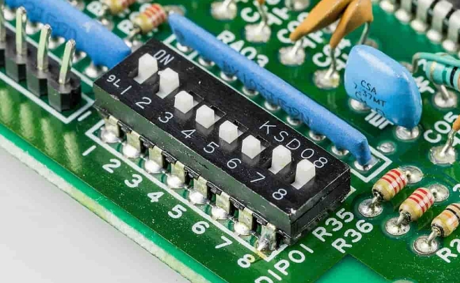
Efficient placement of components is critical when designing high power PCBs. Strategic component placement minimizes trace lengths, reduces parasitic inductance and resistance, and optimizes signal integrity. By carefully considering high power component placement, designers can minimize electromagnetic interference (EMI) and optimize power distribution across the board.
To create high-performance PCBs for high power applications, several critical factors must be addressed during the design process. Attention to detail and adherence to best practices are essential for achieving optimal performance and reliability.
Proper power design is crucial to prevent voltage drops, power loss, and excessive heat generation. Calculating appropriate trace widths based on the expected current flow is vital for minimizing resistive losses and ensuring adequate power delivery to components. Utilizing wider traces for high power connections reduces resistance and avoids voltage drops.
Ground planes play a pivotal role in high power PCBs and should be designed with careful consideration. A solid ground plane beneath signal traces helps minimize noise, coupled signals, and EMI. Furthermore, it aids in effective heat dissipation and forms a low impedance reference point for return current.
Efficient thermal management is critical for ensuring the longevity and reliability of high power PCBs. Excessive heat can lead to component degradation, reduced lifespan, and potential failure. To facilitate effective heat dissipation, thermal reliefs, thermal vias, and proper component placement in relation to heat-generating elements should be employed.
Solder mask is an integral part of PCB design and offers numerous benefits, particularly in high power applications. Its primary function is to protect the copper traces from oxidation, moisture, and contaminants. Selecting high-temperature solder mask materials ensures that the PCB can withstand elevated temperatures associated with high power circuits.
Designing a high-power PCB requires a systematic approach to ensure optimal performance and reliability. Following a step-by-step design process helps streamline the development and minimize potential issues.
At the onset of any design project, clearly identifying the requirements and constraints is crucial. Determine the voltage, current, temperature rise limits, form factor, and other specifications necessary for the PCB design process.
Create a comprehensive schematic capturing the circuit's functionality and identify suitable components for the high power application. Account for component ratings, footprints, and thermal characteristics during the selection process.
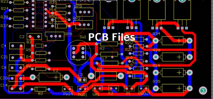
Translating the schematic into a physical layout is a key phase in PCB design. Carefully place components on the board, considering power, signal, and ground integrity. Route traces following proper design rules and guidelines, ensuring optimal signal integrity and power delivery.
Perform thermal analysis using simulation tools to identify potential hotspots on the board. Optimize component placement, power planes, and copper pour areas to distribute heat evenly and prevent localized temperature rise.
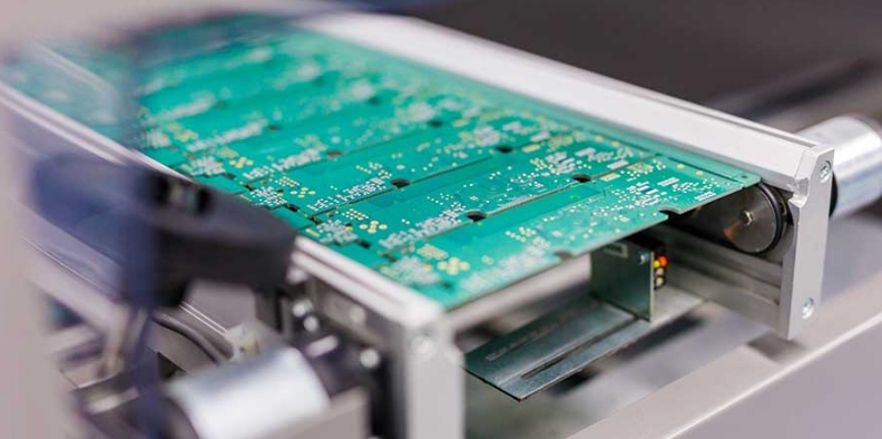
Once the layout is finalized, fabricate a prototype for testing and validation. Verify the design's functionality, thermal performance, and overall reliability through rigorous testing procedures.
Designing PCBs for high power applications requires a comprehensive understanding of various design considerations and best practices. Effective power design, strategic component placement, thermal management, and proper solder mask selection are all essential aspects to ensure optimal performance, reliability, and safety. By adhering to the guidelines outlined in this article, engineers and designers can create high power PCBs capable of meeting the demands of modern high power applications.
Q1: What is the significance of trace width in high power PCB design?
A1: Trace width plays a crucial role in high power PCBs as it directly affects power delivery and efficiency. Wider traces minimize resistance and prevent excessive heat generation.
Q2: How can I achieve effective heat dissipation in high power PCBs?
A2: Proper thermal management can be achieved through strategic component placement, thermal reliefs, thermal vias, and the use of substantial copper areas to enhance heat dissipation.
Q3: What are the challenges associated with high power components placement?
A3: High power component placement requires careful consideration of trace lengths, minimizing parasitic inductance and resistance, optimizing signal integrity, and reducing electromagnetic interference.
Q4: Can I use standard PCB design techniques for high power applications?
A4: While some design principles apply universally, high power PCBs require specialized techniques considering power dissipation, trace widths, thermal management, and grounding techniques.
Q5: Why is solder mask selection crucial in high power PCB design?
A5: Solder mask selection is essential for protecting copper traces from oxidation, moisture, and contaminants. Choosing high-temperature solder masks ensures elevated temperature tolerance necessary for high power applications.