Professional China PCB Assembly Online Services
In today's fast-paced technological landscape, electronic devices demand more efficiency, compactness, and flexibility than ever before. This need for innovation has led to the emergence and widespread adoption of rigid flex printed circuit boards (PCBs). Rigid flex PCBs, a revolutionary blend of rigid and flexible circuitry, have opened doors to new design possibilities and enhanced performance across various industries.
What makes rigid flex PCBs so remarkable? What are the advantages and applications that make them a preferred choice for cutting-edge electronics? Let's explore the fascinating world of rigid flex PCBs and unlock the potential they hold.

To comprehend the intricacies of rigid flex PCBs, it is vital to understand the fabrication process involved. Rigid flex PCB fabrication goes beyond the conventional two-dimensional manufacturing methods, offering designers comprehensive flexibility in achieving their desired form and function.
The fabrication process begins with careful material selection. Choosing the right substrate and adhesive materials allows for optimal performance and durability. The layer stack-up design comes next, where the circuit designer decides on the arrangement of the rigid and flexible layers.
During circuit layout, designers must consider the unique characteristics of rigid flex PCBs. Proper planning of component placement, routing, and traces ensures the integrity and reliability of the final product.
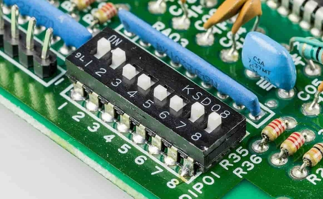
Among the various materials used in rigid flex PCBs, FR4 boards play a pivotal role. FR4, a flame-resistant epoxy laminate, offers excellent mechanical strength, electrical insulation, and thermal resistance. These characteristics make FR4 boards ideal for flexible circuits that require both reliability and flexibility.
The benefits of FR4 boards extend beyond their mechanical properties. Their compatibility with high-density designs, ease of fabrication, and cost-effectiveness make them a popular choice across diverse applications.
Rigid flex PCBs consist of both flexible and rigid layers, making them a unique breed of circuit boards. The flexible layers, often made of polyimide, provide the necessary bending and folding capabilities, enabling the PCB to fit into intricate spaces. On the other hand, rigid layers, typically constructed using FR4 or other rigid materials, offer stability and support to the board.
For optimal functionality, circuit substrates also play a vital role in rigid flex PCBs. The choice of substrate material and its quality greatly impact the overall reliability and performance of the final product. Attention to detail is crucial when selecting and designing these circuit substrates.
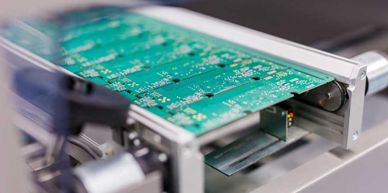
Rigid flex PCB manufacturing undergoes a meticulous process that guarantees precision and performance. Let's walk through the essential steps involved in bringing a rigid flex PCB to life:
Preparing the materials and design files: Gathering the necessary materials, including rigid and flexible layers, adhesive materials, and design files, is the first step in the manufacturing process.
Inner layer processing: The inner layer goes through processes like cleaning, coating, imaging, etching, and even desmearing for optimal adhesion between layers.
Lamination and bonding: This step involves combining the different layers, including the rigid and flex layers, using heat and pressure to create a unified circuit board.
Drilling and through-hole plating: Precise drilling of holes is essential in rigid flex PCBs to ensure component placement accuracy. Through-hole plating strengthens the holes and facilitates efficient electrical connections.
Etching and stripping: The etching process removes excessive copper, while stripping removes any remaining unwanted materials from the board's surface.
Surface finish and solder mask application: Applying surface finish, commonly known as the protective coating, increases the PCB's lifespan. Solder mask application ensures electrical isolation and safeguards against solder bridges.
As the demand for more complex and functional electronic devices grows, the need for multilayer flex PCBs becomes evident. Multilayer flex PCBs offer the ability to add multiple layers of flexible circuitry, increasing the design possibilities and enhancing the overall functionality of electronic devices.
One of the primary advantages of using multilayer flex PCBs is the ability to accommodate a larger number of components and interconnects within a smaller form factor. The additional layers allow for more efficient use of space, enabling designers to create compact and highly integrated electronic assemblies.
However, incorporating multiple layers in a flexible substrate poses certain challenges. Ensuring proper alignment and interconnection between the layers requires precision and expertise. Moreover, managing heat dissipation and maintaining signal integrity become critical factors in the design and fabrication process.
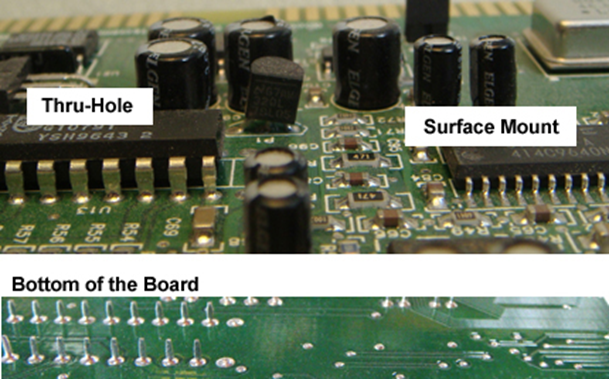
Once the rigid flex PCBs are fabricated, the next step is assembly, where the components are mounted onto the board and interconnected to create a functional electronic circuit. PCB assembly for rigid flex boards involves a combination of surface mount technology (SMT) and through-hole processes.
SMT is the primary method used for mounting components onto rigid flex PCBs. This technique involves placing surface mount components onto designated pads on the board and soldering them in place. SMT offers advantages such as smaller component sizes, increased component density, and faster assembly times.
However, certain components, such as connectors and larger components, may require through-hole mounting. Through-hole mounting involves inserting component leads through pre-drilled holes on the board and soldering them on the opposite side. This process provides additional mechanical stability and robustness to the assembly.
During the assembly process, challenges may arise, such as handling the flexible portions of the board, ensuring proper solder joint formation, and minimizing stress on the flex areas. Special techniques and equipment are employed to address these challenges and ensure high-quality assembly.
Designing rigid flex PCBs requires careful consideration of various factors to ensure optimal performance and reliability. Here are some best practices and tips for successful rigid flex PCB design:
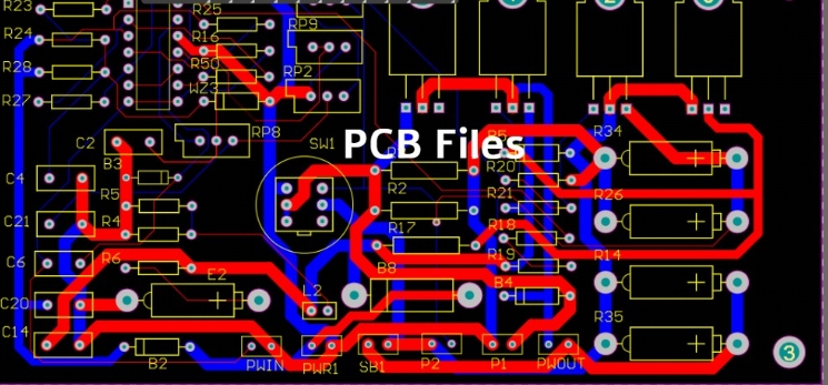
PCB design guidelines for rigid flex boards: Familiarize yourself with the design guidelines provided by PCB manufacturers. These guidelines outline specific requirements regarding dimensions, trace widths, copper clearances, and other design parameters.
Routing and trace considerations: When routing traces on flexible sections, avoid sharp corners or acute angles to prevent stress concentration. Use gradual curves or fillets instead. Additionally, use wider traces on flexible areas to minimize resistance and enhance flexibility.
Thermal management in rigid flex PCBs: Pay attention to heat dissipation in rigid flex PCBs. Consider the placement of heat-generating components, incorporate thermal vias and copper planes for heat distribution, and ensure proper airflow in the overall device design.
Following these best practices and tips can significantly improve the manufacturability and reliability of rigid flex PCBs, leading to successful product development.
While designing rigid flex PCBs, designers often encounter specific challenges that require careful consideration and problem-solving. Here are some common design challenges and tips for overcoming them:
Bending and folding limitations: Rigid flex PCBs are designed to withstand a certain number of bending and folding cycles. Exceeding these limitations can result in damage to the flexible portions or the circuitry. It is important to analyze the expected flexing conditions and ensure that the design can withstand the anticipated stress.
Component placement and solder joint concerns: Dense component placement can lead to challenges during assembly and solder joint formation. Proper component spacing, considering the size and type of components, is crucial to ensure optimal soldering and reduce the risk of short circuits or electrical failures.
Minimizing stress on flex areas: Careful management of stress on the flexible parts of the board is essential. Choose the appropriate substrate material, ensure proper support for components and connectors, and avoid applying excessive force or tension during installation.
Addressing these design challenges early in the development process will help mitigate potential issues and ensure the overall reliability and functionality of rigid flex PCBs.
Solder mask, also known as solder resist, plays a vital role in rigid flex PCBs. It is a protective layer applied to the circuit board's surface, covering the copper traces and pads, except for areas where soldering is required. The primary purpose of the solder mask is to provide electrical insulation and prevent solder bridges, which can cause short circuits.
In rigid flex PCBs, the solder mask serves an additional role of safeguarding the flexible portions of the board. The solder mask acts as a protective barrier, preventing mechanical stress or damage during handling and assembly processes. It also provides a level of protection against environmental factors such as moisture, dust, and chemical contaminants.
Using solder mask in rigid flex PCBs offers several benefits. It improves the overall reliability and lifespan of the board by preventing accidental solder connections and reducing the risk of damage. The solder mask also enhances the PCB's appearance by providing a uniform and professional look.
As technology continues to advance, so does the field of rigid flex PCB fabrication. New and innovative technologies are constantly being developed to push the boundaries of what is possible with rigid flex PCBs. Let's explore some cutting-edge technologies that are shaping the future of rigid flex fabrication.
Emerging trends and advancements: Industry experts are exploring advancements in materials, such as conductive inks and nanomaterials, to enhance the performance and flexibility of rigid flex PCBs.
Flex-to-install technology: Flex-to-install technology aims to simplify the installation process of rigid flex PCBs in devices by allowing the board to conform to a specific shape or contour during assembly.
Challenges and future prospects: While the field of rigid flex fabrication continues to evolve, challenges remain. These include refining the manufacturing processes, addressing cost barriers, and educating designers and engineers about the potential of rigid flex technology.
By staying at the forefront of these emerging technologies, designers and manufacturers can harness the full potential of rigid flex PCBs and drive innovation in diverse industries.
To understand the significance of rigid flex PCBs, it is essential to trace the evolution of flexible PCBs. Flexible PCBs, also known as flex circuits, have been a key enabler in making electronic devices smaller, lighter, and more flexible.
Flexible PCBs were initially developed to replace traditional wire harnesses, reducing manufacturing complexity and improving reliability. Over time, advancements in material science, circuit fabrication techniques, and design capabilities have expanded the application possibilities of flexible PCBs.
Today, flexible PCBs are widely used in various industries, including automotive, aerospace, medical devices, and consumer electronics. Their ability to conform to unique shapes and tolerate extreme conditions has opened up exciting opportunities for innovation.
As with any technological innovation, rigid flex PCBs come with their own set of pros and cons. Understanding these advantages and limitations is crucial for designers, engineers, and manufacturers exploring the possibilities of rigid flex technology.
Advantages of rigid flex PCBs: Rigid flex PCBs offer increased design flexibility, reduced weight and size, improved reliability, and enhanced signal integrity. They can withstand high levels of mechanical stress, temperature variations, and challenging environmental conditions.
Limitations and considerations: Rigid flex PCBs require specialized design expertise and manufacturing processes, which may add to the overall development time and cost. Additionally, the complex nature of rigid flex PCBs may pose challenges during repair or modification.
By carefully considering the specific requirements and constraints of the project, designers can evaluate whether rigid flex PCBs are the right solution for their application.
Rigid flex PCB fabrication represents the future of electronics, offering unmatched design freedom, improved reliability, and enhanced performance. Through careful material selection, precision in fabrication processes, and adherence to design best practices, the potential of rigid flex technology can be fully realized.
As the demand for smaller, more flexible, and highly functional electronic devices continues to grow, the capabilities of rigid flex PCBs will play an increasingly pivotal role in shaping the landscape of the electronics industry. It is an exciting time for innovation and exploration in rigid flex PCB fabrication, and the possibilities are vast.