Professional China PCB Assembly Online Services
In the intricate world of electronics, Printed Circuit Boards (PCBs) are the backbone that brings technology to life. Among the various configurations, the 4 layer PCB stackup stands out as a versatile solution, balancing cost-effectiveness with performance. With a thickness of 1.6 millimeters, this design standard strikes the perfect chord between mechanical stability and functionality. In this beginner-friendly guide, we’ll demystify the 4 layer PCB stackup, exploring its components, advantages, and key considerations for design, all while keeping the language simple and accessible.

A 4 layer PCB consists of—unsurprisingly—four layers of material sandwiched together. These layers are strategically organized to optimize signal integrity, power distribution, and reduce electromagnetic interference (EMI). Here’s a breakdown:
1. Signal Layer (Top): This is where most of your circuit’s components are placed and connected via copper traces. It’s the outermost visible layer and handles primary signal routing.
2. Ground Plane: Below the top signal layer lies the first inner layer, often dedicated as a ground plane. It provides a continuous return path for signals, reducing noise and improving signal quality.
3. Power Plane: Sandwiched between the two inner layers, the power plane supplies steady voltage to the components. Like the ground plane, it covers a large area, enhancing power delivery and reducing voltage drops.
4. Signal Layer (Bottom): Mirroring the top layer, the bottom signal layer allows for additional routing space. It's particularly useful for complex designs or when needing to keep high-speed signals separated.
The 1.6mm thickness is a widely accepted industry standard for several reasons:
Mechanical Stability: Thicker boards offer better resilience against bending and warping during assembly or in use, ensuring longevity and reliability.
Compatibility: Many off-the-shelf components and connectors are designed with a 1.6mm board in mind, simplifying the manufacturing process and reducing custom tooling costs.
Cooling Efficiency: Adequate thickness promotes efficient heat dissipation, crucial for components that generate significant heat during operation.
To make the most of your 4 layer PCB, consider these essential design pointers:
Layer Allocation: Strategically assign signal types to layers. High-speed signals should be routed on internal layers surrounded by ground planes to minimize crosstalk and EMI.
Vias and Traces: Use blind and buried vias sparingly to maintain cost-effectiveness. Optimize trace width and spacing based on current carrying capacity and signal frequency.
Power and Ground Planes: Keep them solid without cuts wherever possible to ensure a consistent reference plane. Use stitching vias to connect the planes at regular intervals, further reducing noise.
Signal Integrity: Implement proper impedance control, especially for high-speed signals, to prevent reflections and ensure signal quality.
Thermal Management: Incorporate thermal relief patterns for large pads to facilitate soldering while managing heat dissipation effectively.
Designing a 4 layer PCB stackup with a 1.6mm thickness is a balancing act between performance, cost, and manufacturability. By understanding the roles of each layer, adhering to best practices, and carefully considering the design elements outlined above, you can create a robust, efficient PCB that stands the test of time. Remember, every decision in the design process contributes to the overall functionality and reliability of your electronic device, making thorough planning and execution paramount. With this guide, you're well-equipped to embark on your journey towards crafting environmentally conscious, high-performance PCBs.
1. What is the primary advantage of using a 4 layer PCB stackup compared to a 2 layer design?
The 4 layer PCB offers several advantages over a 2 layer design, including improved signal integrity due to dedicated ground and power planes. This separation reduces cross-talk and electromagnetic interference (EMI), enabling higher speed signaling. Additionally, it allows for more complex routing, better power distribution, and more efficient heat management.
2. How does the 1.6mm thickness impact the manufacturing cost of a 4 layer PCB?
The 1.6mm thickness is a common standard in PCB manufacturing, meaning it doesn’t typically add extra cost compared to non-standard thicknesses. It ensures compatibility with standard component footprints and off-the-shelf hardware, reducing the need for custom tooling. However, overall cost still depends on other factors like board size, complexity, and production volume.
3. Can I have mixed signal and power layers in a 4 layer PCB stackup, or should they be kept separate?
Ideally, you should keep signal layers separate from power and ground layers. The inner layers are typically dedicated to power and ground planes to provide a stable voltage reference and minimize noise. Signal layers are usually placed on the outer layers. Mixing signal and power layers can increase crosstalk and EMI issues, affecting signal quality.
4. How do I decide which signals to route on the top and bottom layers versus the inner layers?
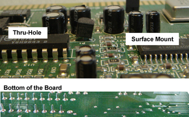
High-speed signals and those requiring controlled impedance should be routed on the inner layers, surrounded by ground planes. This configuration minimizes signal degradation and interference. Less critical signals, connector pins, and components that require through-hole mounting are typically placed on the outer layers for easier access and lower manufacturing complexity.
5. Are there any specific design software recommendations for creating a 4 layer PCB stackup with a 1.6mm thickness?
Popular PCB design software packages like Altium Designer, Eagle by Autodesk, KiCad, and PADS by Siemens all support designing 4 layer PCBs with customizable thickness settings. Each has its own strengths, so choosing one depends on factors such as your familiarity with the software, project requirements, available features, and cost.
6. How does the thickness of a 4 layer PCB affect its flexibility?
Generally, a thicker PCB (like 1.6mm) is less flexible than a thinner one, which can be beneficial for applications where rigidity is important to prevent damage during handling or installation. However, increased thickness may not be ideal for applications requiring extreme flexibility, like wearable technology or devices that need to conform to irregular surfaces.
7. Is it possible to modify the layer stackup (e.g., adding more ground layers) while maintaining the 1.6mm thickness?
Yes, while keeping the total thickness at 1.6mm, you can adjust the layer composition within the stackup. For example, you could have two signal layers, one power plane, and two ground planes for enhanced shielding. However, such modifications might require adjusting the thickness of each individual layer, which should be done in consultation with your manufacturer to ensure feasibility and adherence to manufacturing standards.