Professional China PCB Assembly Online Services
Printed Circuit Boards (PCBs) are integral to the functioning of modern electronic devices. Among the various layers and components of a PCB, the silkscreen layer plays a crucial role in providing essential information for assembly, testing, and troubleshooting. In this article, we will explore the importance of silkscreen on a PCB, the materials and methods used in its application, and best practices for designing and utilizing silkscreen markings.

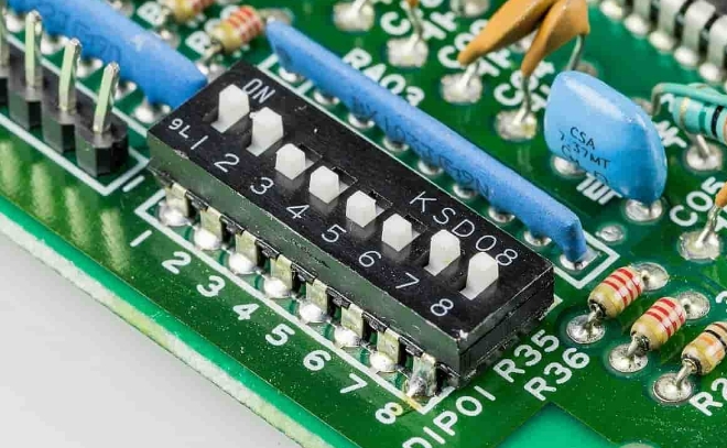
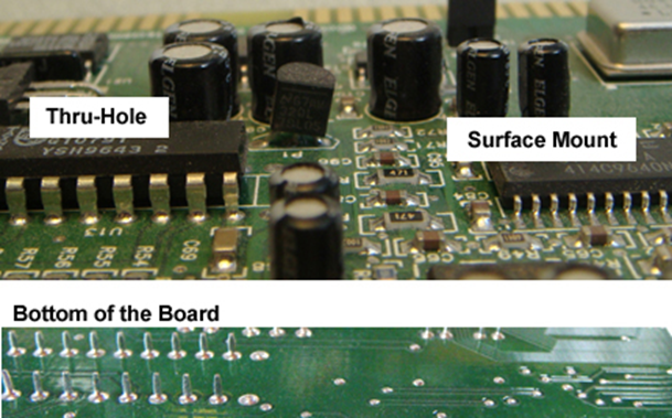
Silkscreen is a layer of ink traces applied to the surface of a PCB to provide labels and identifiers for various components, test points, and other critical areas. This layer is typically found on both the top and bottom sides of the PCB and is essential for PCB assembly and maintenance. The silkscreen layer includes reference designators, component outlines, logos, and other markings that aid in identifying and placing components correctly.
The ink used for silkscreen printing on PCBs is typically acrylic ink, known for its durability and resistance to environmental factors. Acrylic ink provides clear and legible markings that can withstand the soldering process and other harsh conditions during PCB manufacturing and operation.
Another type of ink used is conductive epoxy ink, which can provide electrical conductivity for certain applications. However, this is less common for standard silkscreen applications and is typically used for specialized purposes.
There are several methods for applying silkscreen to a PCB, each with its own advantages and applications. The most common methods include:
Manual screen printing is a traditional method where a stencil (screen) is used to apply the ink onto the PCB. The screen has the desired pattern, and ink is pushed through the screen onto the board. This method is cost-effective for small production runs but may not be suitable for high-precision requirements due to potential inconsistencies in ink application.
Liquid Photo Imaging (LPI) and Direct Legend Printing (DLP) are more advanced methods that offer higher precision and consistency.
LPI involves applying a liquid photoresist to the PCB, which is then exposed to UV light through a photomask with the desired pattern. The exposed areas harden, and the unexposed areas are washed away, leaving the silkscreen pattern.
DLP uses an inkjet projector to directly apply the ink onto the PCB. This method is highly accurate and allows for fine line widths and detailed markings.
Inkjet printing is a modern method that uses an inkjet projector to apply the silkscreen ink directly onto the PCB. This method is highly flexible and can produce very fine details. The ink is cured using UV light, ensuring durability and resistance to environmental factors.
The silkscreen printing process involves several steps to ensure the accuracy and durability of the markings:
1. Design Preparation: The silkscreen design is created using PCB design software. This includes placing reference designators, component outlines, and other necessary markings.
2. Screen Preparation: For manual screen printing, a screen with the desired pattern is prepared. For LPI and DLP, photomasks or digital patterns are created.
3. Ink Application: The ink is applied to the PCB using the chosen method (manual screening, LPI, DLP, or inkjet printing).
4. Curing: The ink is cured using UV light to ensure it adheres properly to the PCB and can withstand the manufacturing process.
5. Inspection: The silkscreen layer is inspected for accuracy and completeness to ensure all markings are clear and legible.
Ensure that all silkscreen markings are clear and legible. Use appropriate font sizes and line widths to ensure that the text and symbols can be easily read during assembly and testing.
Avoid placing silkscreen markings on critical areas such as pads, vias, and solder mask openings. This prevents interference with soldering and electrical connections.
Use standard reference designators (e.g., R for resistors, C for capacitors) to make it easier for engineers and technicians to identify components during assembly and troubleshooting.
Include test points in the silkscreen layer to facilitate testing and debugging. Clearly label these points to ensure they can be easily located.
Optimize the use of silkscreen layers to include all necessary information without overcrowding the PCB. Balance the need for information with the available space on the board.
Silkscreen markings play a vital role in PCB assembly and testing. During assembly, the silkscreen layer provides guidance for placing components correctly, ensuring that the right components are placed in the right locations. This reduces the risk of errors and improves the efficiency of the assembly process.
During testing, silkscreen markings help technicians identify test points and other critical areas. This facilitates efficient testing and debugging, allowing for quick identification and resolution of issues.
Silkscreen on a PCB is an essential layer that provides critical information for assembly, testing, and maintenance. By using the right materials and methods, such as acrylic ink and advanced printing techniques like LPI and DLP, designers can ensure that their PCBs are easy to assemble and maintain. Following best practices for silkscreen design and application will result in clear, legible markings that enhance the overall quality and reliability of the PCB.
Incorporating silkscreen layers effectively into your PCB design process will not only improve the assembly and testing phases but also contribute to the long-term reliability and performance of your electronic devices. By paying attention to details and utilizing modern printing techniques, you can create PCBs that are both functional and easy to work with, ensuring success in your electronic projects.
Silkscreen on a PCB provides crucial information such as reference designators, component outlines, test points, and other markings. These help in identifying and placing components correctly during PCB assembly, as well as facilitating testing and troubleshooting.
Acrylic ink is the most commonly used material for silkscreen printing on PCBs due to its durability and resistance to environmental factors. Conductive epoxy ink is also used for specialized applications where electrical conductivity is required.
The primary methods of applying silkscreen to a PCB include manual screen printing, Liquid Photo Imaging (LPI), Direct Legend Printing (DLP), and inkjet printing. Each method has its own advantages in terms of precision, cost, and suitability for different production volumes.
Liquid Photo Imaging (LPI) involves applying a liquid photoresist to the PCB, which is then exposed to UV light through a photomask. The exposed areas harden, and the unexposed areas are washed away, leaving the desired silkscreen pattern.
UV light is used to cure the ink applied during silkscreen printing. This curing process ensures that the ink adheres properly to the PCB, making the markings durable and resistant to environmental factors.
Placing silkscreen markings on critical areas such as pads, vias, and solder mask openings can interfere with soldering and electrical connections. It is important to avoid these areas to ensure the proper functioning of the PCB.
Reference designators are labels used to identify components on a PCB (e.g., R for resistors, C for capacitors). They are important because they provide a standardized way to identify components, making assembly, testing, and troubleshooting more efficient.
While silkscreen markings themselves do not affect the electrical performance of a PCB, improper placement of these markings can interfere with soldering and connections. Ensuring that silkscreen markings are placed correctly is essential for maintaining PCB performance.
Inkjet printing offers high precision and flexibility, allowing for very fine details and complex patterns. It is also suitable for both small and large production runs, making it a versatile option for silkscreen application.
To ensure clear and legible silkscreen markings, use appropriate font sizes and line widths, avoid overcrowding the PCB with too much information, and choose high-contrast colors for the ink. Regular inspection and quality control during the printing process also help maintain clarity.
The silkscreen layer provides labels and identifiers for components and test points, while the solder mask layer is a protective coating that prevents solder bridges and short circuits during soldering. Both layers serve different purposes but are crucial for the overall functionality and reliability of the PCB.
Including test points in the silkscreen layer facilitates testing and debugging by providing clear locations for technicians to probe and measure electrical signals. This helps in quickly identifying and resolving issues, improving the efficiency of the testing process.