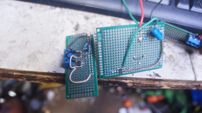
In the dynamic world of electronics, innovation and rapid development are key. One of the pivotal components in this fast-paced industry is the SMT prototype board. Surface Mount Technology (SMT) has revolutionized the way electronic circuits are designed and manufactured, making the development process faster and more efficient. In this article, we will explore what SMT prototype boards are, their importance in electronics, and the steps involved in creating them. We'll also address some common questions to help you better understand this essential technology.

An SMT prototype board, or Surface Mount Technology prototype board, is a type of printed circuit board (PCB) used primarily for testing and developing electronic circuits. Unlike traditional through-hole technology, where components are inserted into drilled holes, SMT involves mounting components directly onto the surface of the board. This allows for more compact designs and greater efficiency in both assembly and performance.
SMT prototype boards play a crucial role in the electronics industry. They allow engineers and designers to test and validate their circuit designs before mass production. By using prototype boards, developers can identify and rectify any issues early in the development cycle, saving time and reducing costs. Additionally, SMT prototype boards enable rapid iteration, allowing for quick modifications and improvements.
Creating an SMT prototype board involves several steps, each critical to ensuring the final product meets the desired specifications and functions correctly. Let's delve into these steps in detail.
The process begins with designing the circuit using specialized software. Engineers create a schematic diagram that outlines the connections and components required for the circuit. Once the schematic is complete, the layout of the PCB is designed. This involves placing the components on the board and routing the electrical connections between them.
Choosing the right materials is essential for the performance and reliability of the SMT prototype board. The most commonly used material for PCBs is FR-4, a composite of fiberglass and epoxy resin. This material provides excellent mechanical strength and electrical insulation. For specific applications, other materials such as Rogers or Teflon may be used.
Once the design and materials are finalized, the PCB fabrication process begins. This involves creating the physical board by layering copper and substrate materials. The design is transferred to the board using a photolithography process, which creates the circuit pattern on the copper layers.
The next step is placing the components onto the board. This is done using automated machines that precisely position each component according to the design. Surface mount components are much smaller than their through-hole counterparts, allowing for more compact and efficient designs.
Soldering is a critical step in the SMT process. It involves attaching the components to the board by melting solder paste, which creates a strong electrical and mechanical connection. There are two main methods of soldering in SMT: reflow soldering and wave soldering. Reflow soldering is the most common method used for SMT prototype boards.
Quality control is essential to ensure the SMT prototype board functions correctly. The board undergoes various inspections and tests to identify any defects or issues. This includes visual inspection, automated optical inspection (AOI), and electrical testing. Any defects found are rectified before the board moves to the next stage.
Once the board passes all inspections and tests, it is ready for final assembly. This involves adding any additional components or connectors required for the specific application. The completed SMT prototype board is then ready for testing and validation in the intended environment.
SMT prototype boards offer several advantages over traditional through-hole technology, making them the preferred choice for modern electronic designs.
Surface mount components are smaller and can be placed closer together, allowing for more compact and lightweight designs. This is particularly important for portable and wearable devices.
SMT allows for a higher component density on the board, enabling more functionality in a smaller area. This is essential for complex and feature-rich electronic devices.
The automated placement and soldering processes used in SMT are faster and more efficient than manual assembly methods. This reduces production time and costs, allowing for quicker prototyping and iteration.
SMT components generally have better electrical performance due to shorter lead lengths and lower parasitic inductance and capacitance. This results in improved signal integrity and reduced noise.
SMT prototype boards are used in a wide range of applications across various industries. Some common examples include:
Devices such as smartphones, tablets, and laptops rely heavily on SMT prototype boards for their compact and feature-rich designs.
Medical devices, including diagnostic equipment and wearable health monitors, use SMT prototype boards for their reliability and performance.
Modern vehicles incorporate numerous electronic systems, from infotainment to advanced driver-assistance systems (ADAS). SMT prototype boards are essential for developing and testing these systems.
Automation and control systems in industrial settings use SMT prototype boards for their durability and precision.
An SMT prototype board is a type of PCB used for testing and developing electronic circuits. It involves mounting components directly onto the surface of the board using Surface Mount Technology.
SMT prototype boards allow engineers to test and validate their circuit designs before mass production. This helps identify and rectify issues early, saving time and reducing costs.
The most commonly used material is FR-4, a composite of fiberglass and epoxy resin. Other materials such as Rogers or Teflon may be used for specific applications.
The main steps include design and layout, material selection, fabrication, component placement, soldering, inspection and testing, and final assembly.
Benefits include compact design, higher component density, faster assembly, and improved performance due to better electrical characteristics.
Industries such as consumer electronics, medical devices, automotive electronics, and industrial automation use SMT prototype boards for various applications.
In conclusion, SMT prototype boards are a cornerstone of modern electronics development. They enable rapid prototyping, efficient testing, and reliable performance, making them indispensable in today's fast-paced industry. By understanding the process and benefits of SMT prototype boards, engineers and designers can continue to innovate and bring cutting-edge electronic devices to market.