Professional China PCB Assembly Online Services
A multilayer PCB is a printed circuit board that has more than two layers of copper foil and dielectric material. Multilayer PCBs are used for complex and high-density electronic circuits, such as computers, smartphones, and medical devices. Multilayer PCBs offer many advantages, such as:
- Reduced size and weight
- Improved signal integrity and noise reduction
- Increased reliability and durability
- Enhanced functionality and performance
However, multilayer PCBs are also more difficult and expensive to design and manufacture than single or double-sided PCBs. In this article, we will explain the basic steps of how to make a multilayer PCB at home or in a small workshop.

Step 1: Design the Circuit and Generate the Gerber Files
The first step is to design the circuit and generate the Gerber files using a PCB design software, such as Altium Designer, Eagle, or KiCad. The Gerber files are the standard format for communicating the PCB layout to the manufacturer. They contain information about the copper layers, drill holes, solder mask, silkscreen, and other features of the PCB.
The number of layers, the thickness of each layer, the materials used, and the stack-up configuration are some of the important parameters to consider when designing a multilayer PCB. A typical stack-up consists of alternating signal and plane layers, separated by cores and prepregs. Cores are copper-clad laminates that have a fixed thickness and dielectric constant. Prepregs are sheets of fiberglass impregnated with epoxy resin that are semi-cured and can be bonded together under heat and pressure.
The stack-up also determines the impedance values of the traces on different layers. Impedance is the resistance to the flow of alternating current (AC) in a circuit. It depends on factors such as trace width, trace spacing, dielectric thickness, dielectric constant, and frequency. Impedance matching is essential for high-speed signals to avoid signal reflection, distortion, and crosstalk.
Step 2: Print the Circuit on Transfer Paper
The next step is to print the circuit on transfer paper using a laser printer. Transfer paper is a special type of paper that has a coating that can be transferred to another surface by applying heat. The transfer paper should be cut to fit the size of the copper clad that will be used for each layer.
Step 3: Laminate the Copper Clad with Transfer Paper
The third step is to laminate the copper clad with transfer paper using an iron or a laminator. The copper clad is a sheet of copper foil attached to a substrate, such as FR4 or CEM1. The copper clad should be cleaned with acetone or alcohol before laminating to remove any dirt or grease.
The transfer paper should be placed on top of the copper clad with the printed side facing down. The iron or laminator should be set to a high temperature (around 200°C) and applied evenly over the transfer paper for several minutes. The heat will melt the coating on the transfer paper and transfer the circuit image to the copper clad.
Step 4: Etch the Copper Clad
The fourth step is to etch the copper clad using an etching solution, such as ferric chloride or ammonium persulfate. Etching is the process of removing unwanted copper from the copper clad using a chemical reaction. The etching solution should be prepared according to the instructions on the package and poured into a plastic tray.
The copper clad should be immersed in the etching solution with the printed side facing up. The etching solution will dissolve the exposed copper areas that are not covered by the transferred circuit image. The etching process can take from 10 minutes to an hour depending on the concentration of the etching solution, the temperature, and the agitation. The etching process should be monitored carefully to avoid over-etching or under-etching.
Step 5: Remove the Transfer Paper
The fifth step is to remove the transfer paper from the copper clad using acetone or alcohol. The transfer paper should peel off easily after soaking in acetone or alcohol for a few minutes. The remaining circuit image on the copper clad should be rinsed with water and dried with a cloth.
Step 6: Drill Holes for Vias
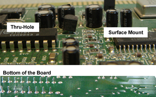
The sixth step is to drill holes for vias using a drill press or a CNC machine. Vias are conductive holes that connect different layers of a multilayer PCB. They can be classified into three types: through-hole vias, blind vias, and buried vias.
Through-hole vias are vias that go through all layers of a multilayer PCB. They are easy to make but occupy more space on both sides of the PCB.
Blind vias are vias that connect an outer layer to one or more inner layers but do not go through the entire PCB. They are more difficult to make but save space on the outer layers.
Buried vias are vias that connect two or more inner layers but do not reach the outer layers. They are the most difficult to make but save space on both sides of the PCB.
The drill holes should be aligned with the pads or traces on the corresponding layers. The drill bits should be chosen according to the size and type of the vias. The drill holes should be cleaned with compressed air or a brush to remove any debris.
Step 7: Plate the Vias
The seventh step is to plate the vias using an electroplating or an electroless plating method. Plating is the process of depositing a thin layer of metal, such as copper, on the surface of another metal, such as copper. Plating is necessary to make the vias conductive and to increase their reliability and durability.
Electroplating is a plating method that uses an electric current to drive the metal ions from a solution onto the surface of another metal. Electroplating requires a power supply, an anode, a cathode, and an electrolyte solution. The anode is the source of metal ions, such as copper sulfate. The cathode is the object to be plated, such as the copper clad with drill holes. The electrolyte solution is a conductive liquid that contains metal ions and other chemicals, such as sulfuric acid.
Electroless plating is a plating method that does not use an electric current but relies on a chemical reaction to deposit metal on another metal. Electroless plating requires a catalyst, a reducing agent, and a plating solution. The catalyst is a substance that initiates and accelerates the chemical reaction, such as palladium chloride. The reducing agent is a substance that provides electrons for the chemical reaction, such as formaldehyde. The plating solution is a liquid that contains metal ions and other chemicals, such as copper sulfate and sodium hydroxide.
Step 8: Apply Solder Mask and Silkscreen
The eighth step is to apply solder mask and silkscreen on the outer layers of the multilayer PCB. Solder mask is a protective layer of resin that prevents solder from bridging between pads or traces during soldering. Solder mask also protects the PCB from corrosion and moisture. Solder mask can be applied using different methods, such as screen printing, spray coating, or dry film lamination.
Silkscreen is a layer of ink that provides labels and symbols on the PCB for identification and assembly purposes. Silkscreen can be applied using different methods, such as screen printing, inkjet printing, or laser printing.
Step 9: Cut and Test the PCB
The final step is to cut and test the PCB using a saw or a CNC machine. The PCB should be cut according to the outline and dimensions specified in the design files. The PCB should also be tested for functionality and quality using different methods, such as visual inspection, electrical testing, or functional testing.
Making a multilayer PCB at home or in a small workshop is possible but challenging. It requires careful planning, precise execution, and proper equipment and materials. However, it can also be rewarding and satisfying for hobbyists and enthusiasts who want to create their own custom electronic devices.